Operating the ADS1115 ADC in continuous mode with Arduino
ADS1115 is a 16-bit delta-sigma analogue to digital converter(ADC) designed by Texas Instruments. It has a maximum sampling rate of 860 samples per second. However, the maximum sampling rate can only be achieved in continuous mode. This article provides an Arduino example of how to interface the ADS1115 in continuous mode.
In continuous mode, the ADS1115 starts the conversion automatically as soon as the last conversion is finished. The chip will also send a signal via the ALERT pin when a conversion is finished. We will attach an interrupt to the ALERT pin and use it to trigger the Arduino to read the conversion result.
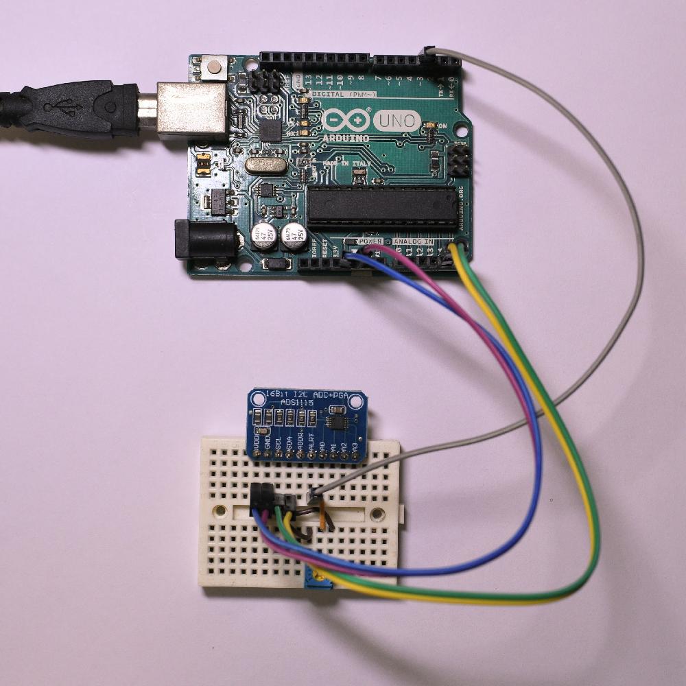
I will use the Arduino Uno in this example, it only supports interrupt on pins 2 and 3. Connect the pins as the following table to the Arduino.
| ADS1115 | Arduino Uno |
|---|---|
| VDD | 5V |
| GND | GND |
| SCL | A5 |
| SDA | A4 |
| ADDR | not connected |
| ALRT | D3 |
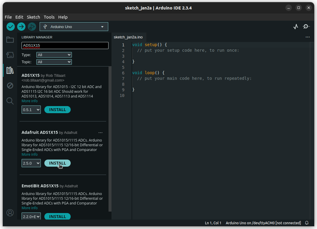
To make our lives easier, let's first install the ADS1X15 library from Adafruit.
First, we need to instantiate an Adafruit_ADS1115 object. We'll also setup some other variables.
#include <Adafruit_ADS1X15.h>

Adafruit_ADS1115 myADS;
unsigned long t0;
int16_t v;
String str;
Next, since we are using interrupt, we need a callback function for the interrupt service routine.
The callback function will set the new_data variable to true when the interrupt is triggered.
const int intPin = 3;
volatile bool new_data = false;
void newDataReady() {
    new_data = true;
}
In the setup() function, we need to:
- Begin serial communication
- Attach interrupt
- Setup ADS1115 for continuous mode
- Read initial time
void setup() {
    Serial.begin(115200);

    // The convertion is ready on the falling edge of a pulse at the ALERT/RDY pin.
    attachInterrupt(digitalPinToInterrupt(intPin), newDataReady, FALLING);

    myADS.begin();
    myADS.setGain(GAIN_FOUR);   // +- 1.024V range
    myADS.setDataRate(RATE_ADS1115_860SPS);
    myADS.startADCReading(ADS1X15_REG_CONFIG_MUX_SINGLE_0, true);
    // We should set "continuous" to true to reach optimal speed.

    t0 = micros();
}
For the serial communication, we need a higher baud rate to send data to the computer fast enough. We'll use 115200 here.
The ALERT pin is connected to intPin, and the interrupt will trigger on the falling edge.
This is because the ADS1115 will pull the ALERT pin low when the conversion is finished.
The key lies in the last line.
In the startADCReading() function, we need to set the second parameter to true, which will put the ADS1115 into continuous mode.
The first parameter selects the channel, we are reading channel 0 single ended in this example.
There are a lot of other setting that you can tweak, see the Adafruit_ADS1X15.h file for more information.
We'll also set the t0 variable to store the initial time in microseconds.
Finally, in the loop() function, we can read the ADS1115 when the new_data variable is true, and print the result through the serial port.
Remember to clear the new_data variable after reading the ADS1115.
I'll also print the time in microseconds to check the sampling rate.
void loop() {
if(!new_data) return;
// Don't call the ADC until we receive a convertion complete signal.

v = myADS.getLastConversionResults();
str = micros() - t0;
str += " ";
str += v;
Serial.println(str);

new_data = false;
}
After uploading the code to the Arduino, we can open the serial monitor to see the result. Remember to set the baud rate to 115200.
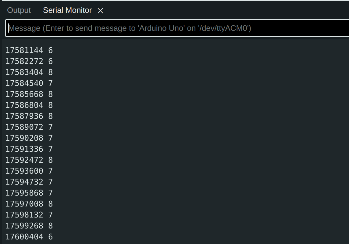
The first column of the output is the time in microseconds. The output of the ADC is printed on the second column. The output of ADS1115 can be both positive and negative depending on the polarity of the input voltage. We can see that the time difference between two lines is around 1130 microseconds, which is just over 860 Hz.