STM32, Arduino environment, ST7735 screen. Bugs and workarounds.
I was working with the ST7735 screen in a project at NTHUEE 822 Maker Space. We were controlling the screen with an STM32F103C8T6 Blue Pill and Adafruit's ST7735 & ST7789 library. And we ran into a very interesting bug, which was caused by the value of "pins" in the STM32 Arduino core. In this article, I will explain the cause of the bug and the workaround for current version of the libraries.
Brief introduction of the ST7735 screen
No, the "ST" in ST7735 does not mean ST Microelectronics. It is a display controller IC made by another company call Sitronix. It communicates with the microcontroller through SPI and some additional signals like data/command and reset. Since we are just using Adafruit's library, I'm not diving into the details of the ST7735. But please remember the reset signal, it will become one of today's focus.
I do have a complaint about the naming of the screen module's pins. Although the screen uses SPI, the communication pins on the module is named as SCL and SDA, which is for I2C. They should be named SCLK and MOSI, respectively.
STM32 Blue Pill & Arduino core
Since most members of our team never used an STM32 before, we decided to use the STM32 Arduino core and programme it with Arduino IDE. We were only making a game, so the trade off between performance and developing time was worth it. To upload the compiled binaries to the STM32, we used a Raspberry Pi Pico as an SWD adapter.
The example code from Adafruit's library
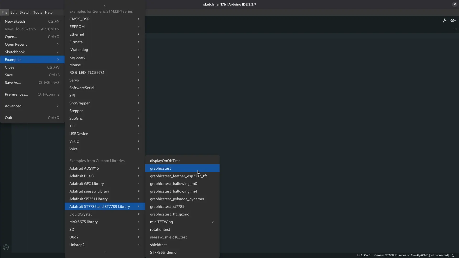
Adafruit wrote an excellent example code (graphicstest) to get us started. It includes a very detailed guide on different ways to initialise the screen and SPI. We can initialise the ST7735 with or without the reset and chip select signals, or use custom SPI pins. I highly recommend reading through all the comments in this example to learn about the library.
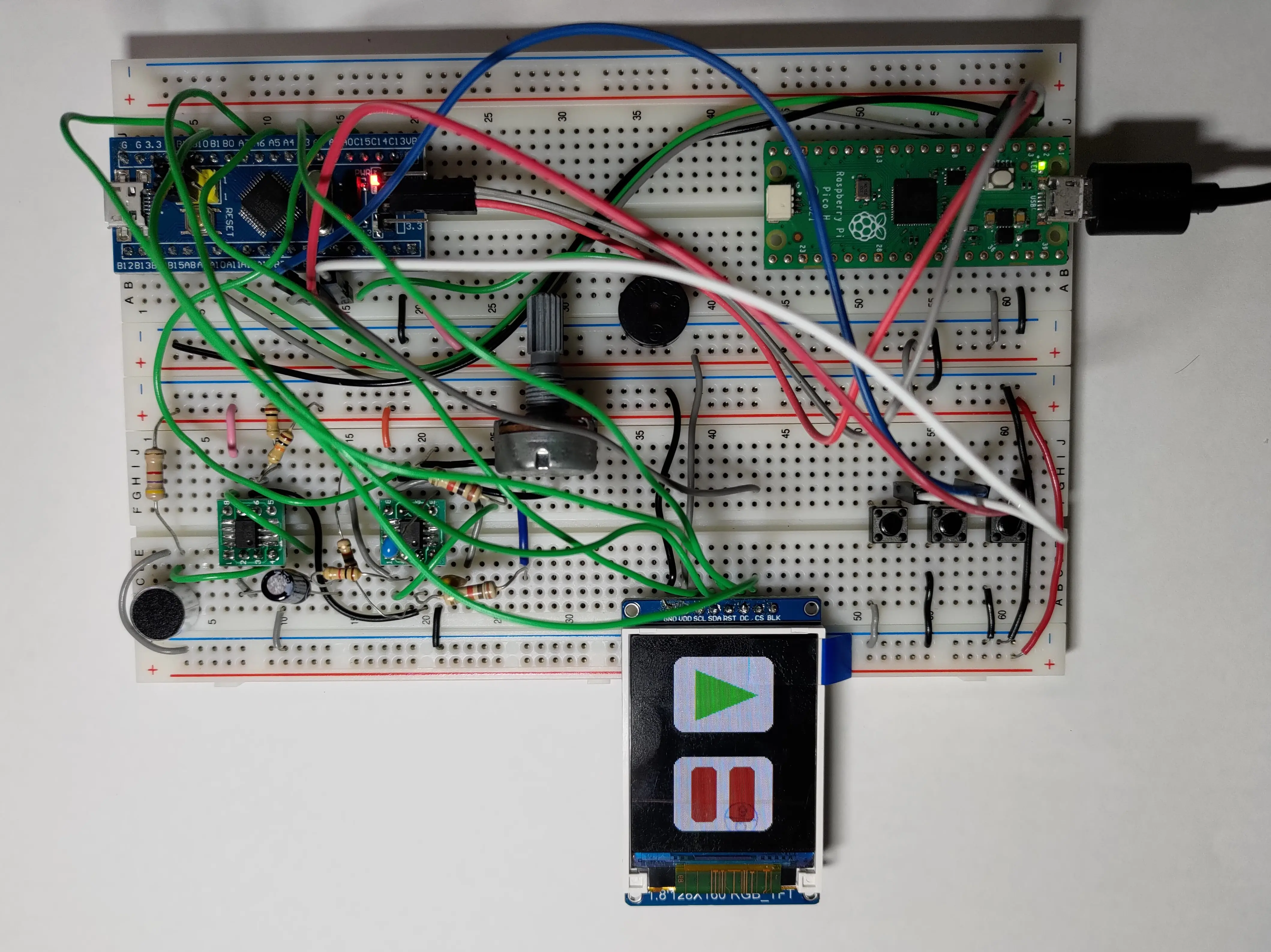
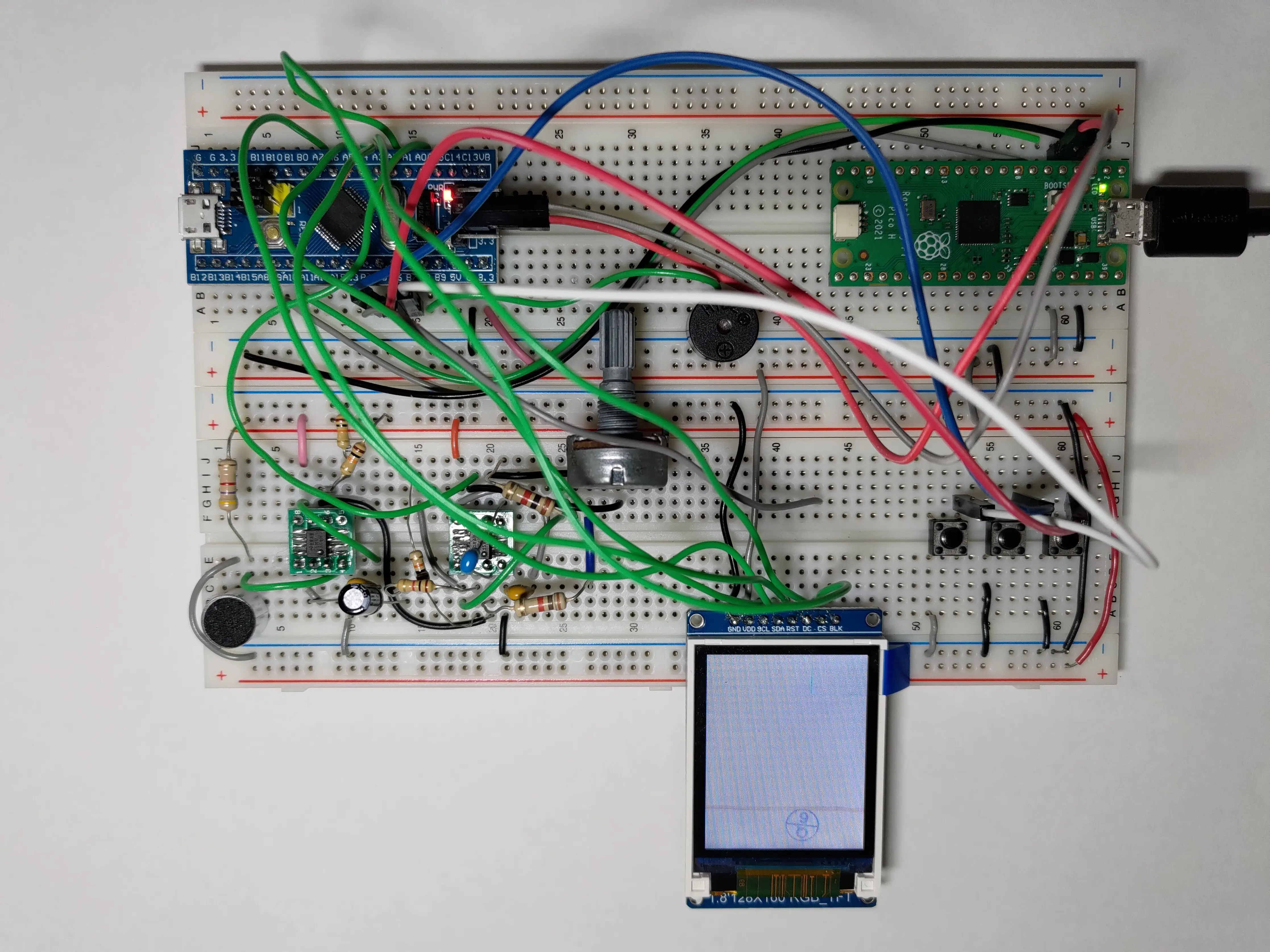
In our initial testing, we used all signals and the default SPI pins on the STM32F103C8T6. The wiring between the Blue Pill and the screen is listed in the table below.
| Screen | STM32 |
|---|---|
| GND | GND |
| VDD | 3.3V |
| SCL | PA5 |
| SDA | PA7 |
| RST | PA4 |
| DC | PA3 |
| CS | PA2 |
| BLK | not connected |
I modified the aforementioned example code to use the correct pins on the STM32.
After compiling and uploading, we were met with a white blank screen. If the example is running correctly, it should look like this (not my video). We recompiled the code for a Raspberry Pi Pico 2 running arduino-pico and the code worked without any issue. Something very weird went wrong.
Investigation
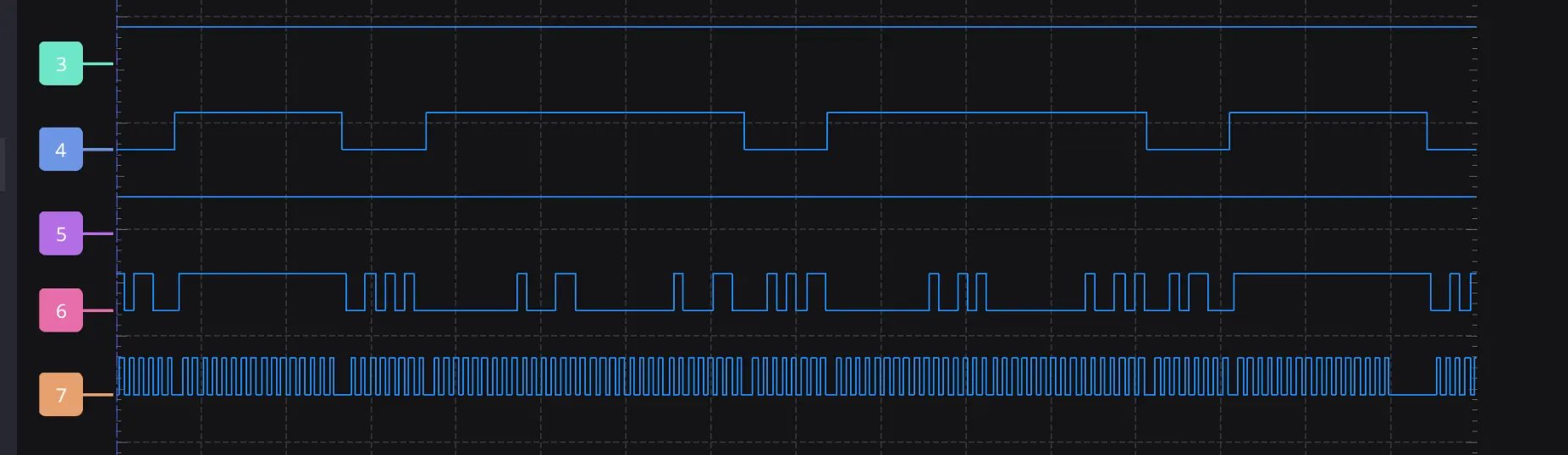
We used a logic analyser to look at the signals between the ST7735 and the STM32. We found two signals being abnormal. First, the chip select signal is always high, which means that the chip is never selected. Second, the reset signal never goes low during startup.
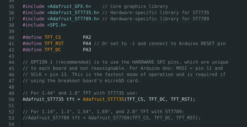
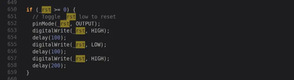
Then, we looked into the source code of the Adafruit ST7735 to figure out what went wrong. The CS and RST pins on the ST7735 is optional in this library and the way to disable it is to set them to -1. However, the Adafruit library actually treats all "negative pin numbers" as disabled, as shown below. But, why will the pin number be negative?
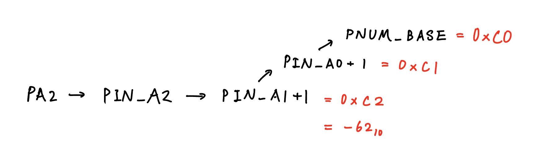
To find out why, we need to look at the definitions in the STM32 Arduino core. What does the macro PA2 actually stand for? It turns out to be 0xC2 in hexadecimal, which is -62 in decimal if intepreted as 8-bit signed integer. Therefore, although we supplied a valid pin number for the CS pin, the library still determines that we are disabling this pin. The same story goes for the RST pin as well.
Workaround
If we look at the pin macro definitions in the STM32 Arduino core, we can find some interesting definitions. The pins that are connected to the ADC has an extra layer of macros, which ultimately lead to value between 0xC0 and 0xC9.
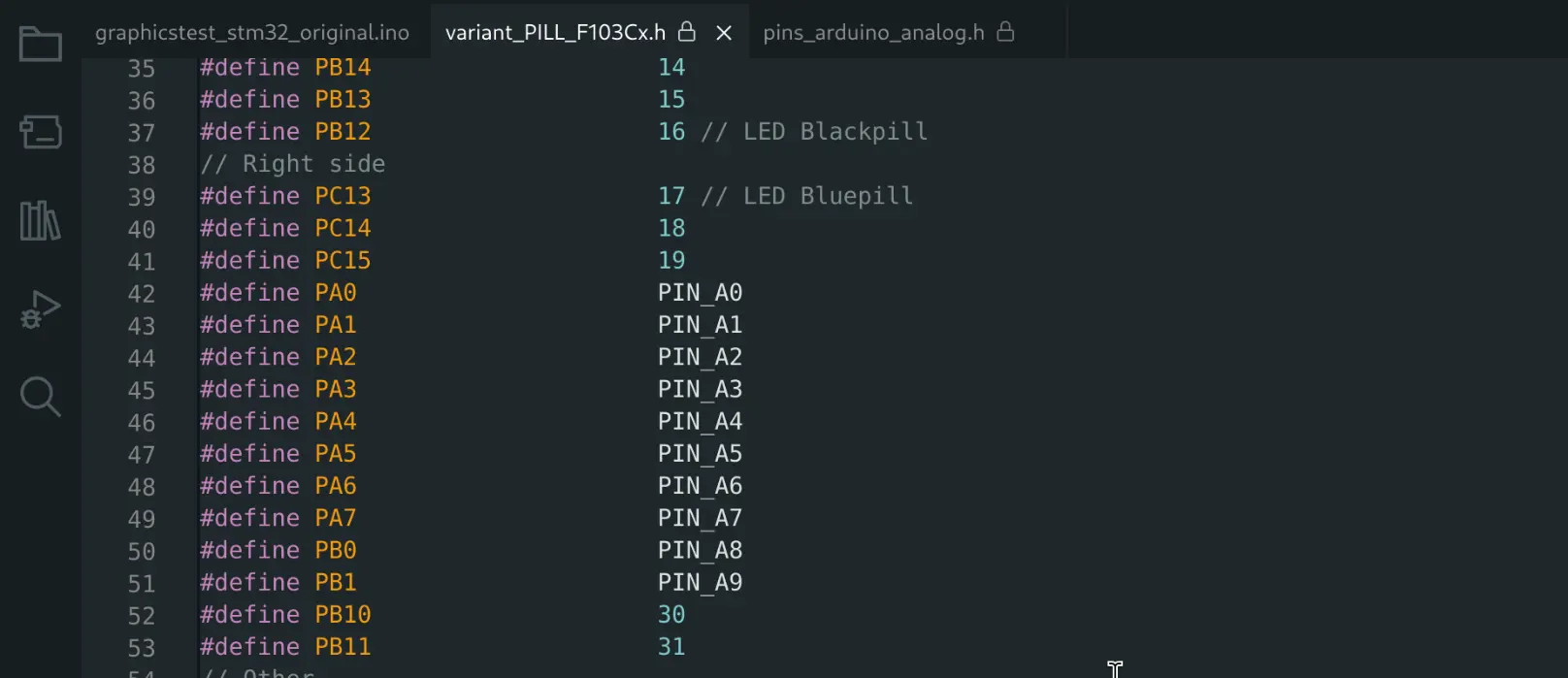
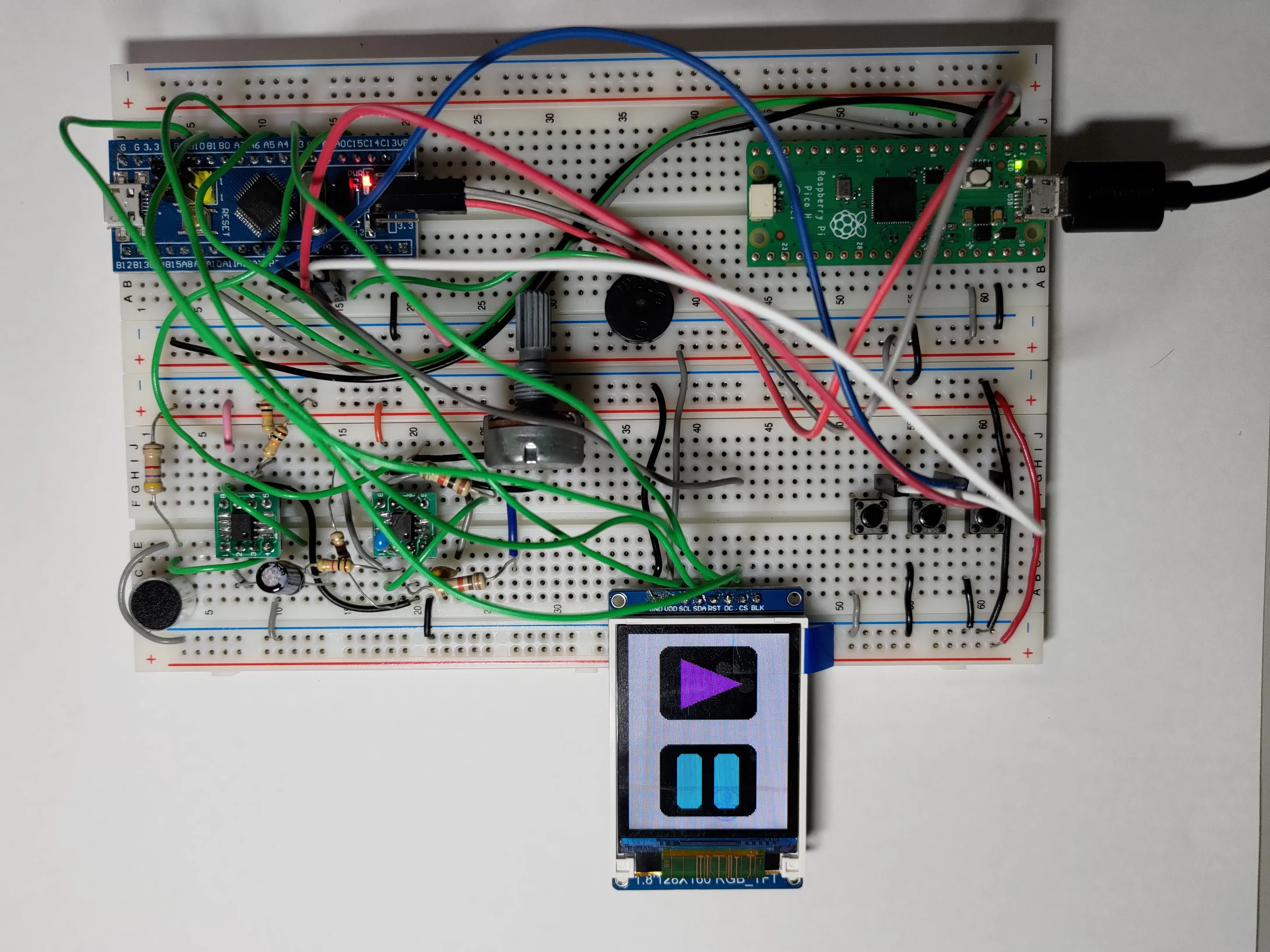
The simple workaround is to avoid PA0 to PA9 for the CS and RST signals. I moved my CS and RST signals to PB11 and PB10, respectively. The updated pin connection is listed below and you can download the code for STM32 with working pin assignment here. This way, the code will run without issue.
| Screen | STM32 |
|---|---|
| GND | GND |
| VDD | 3.3V |
| SCL | PA5 |
| SDA | PA7 |
| RST | PB10 |
| DC | PA3 |
| CS | PB11 |
| BLK | not connected |