SPICE simulation with Kicad
Kicad is an open-source electronics design suite, mainly used in PCB design. It also has built-in Ngspice simulator to simulator circuit behaviours. In this article, we will go through the basic setup of SPICE simulation in Kicad and how to find extra SPICE models.
Schematic
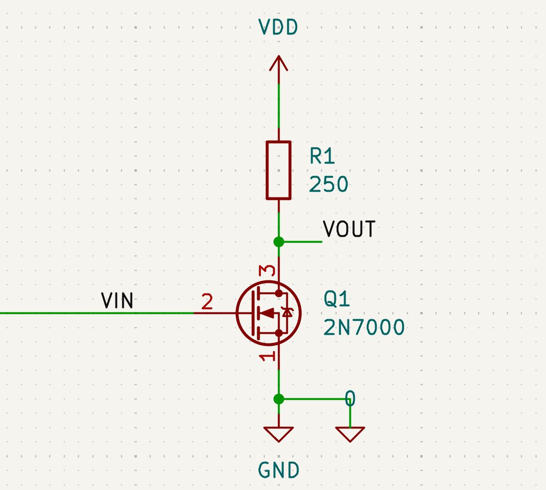
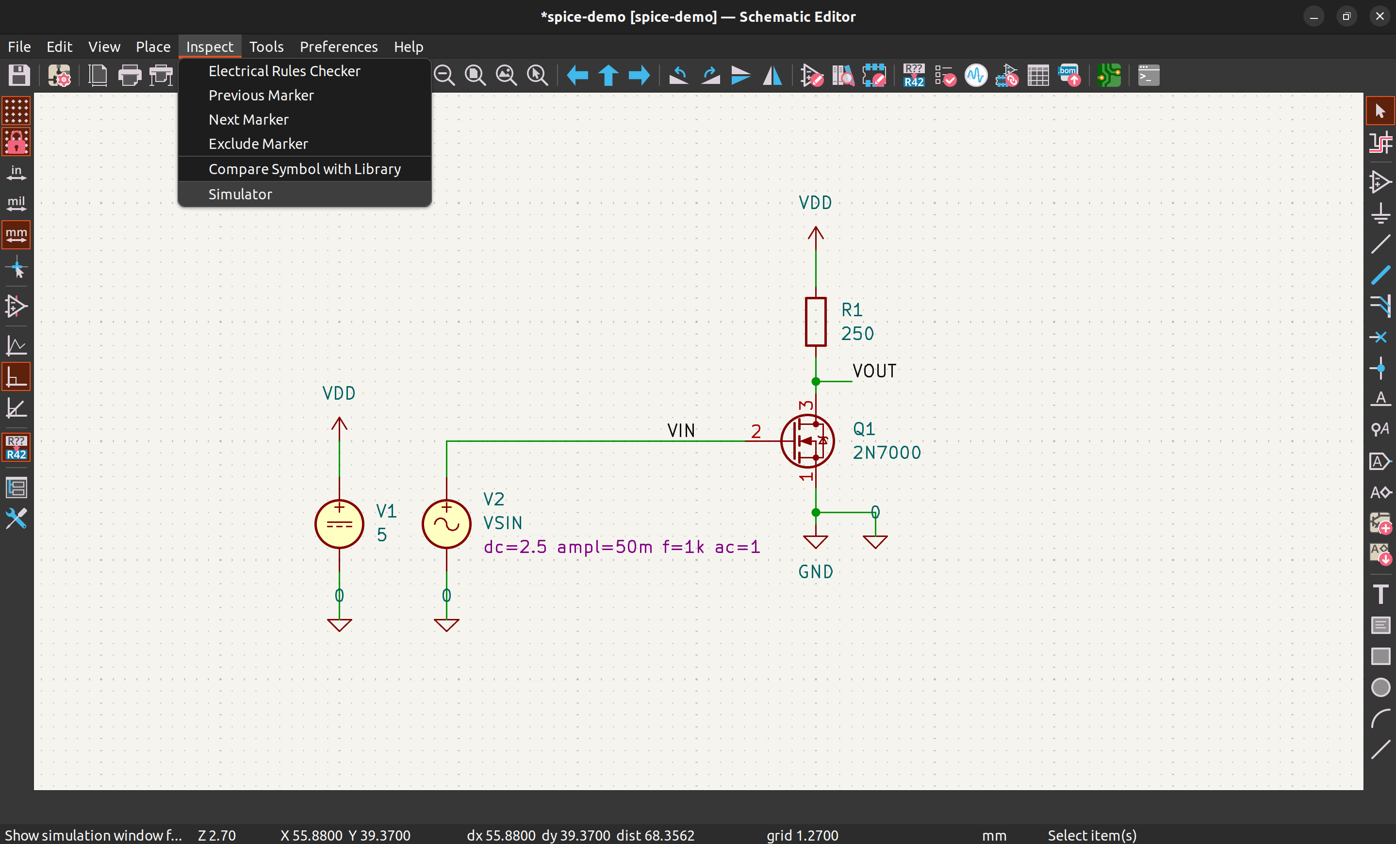
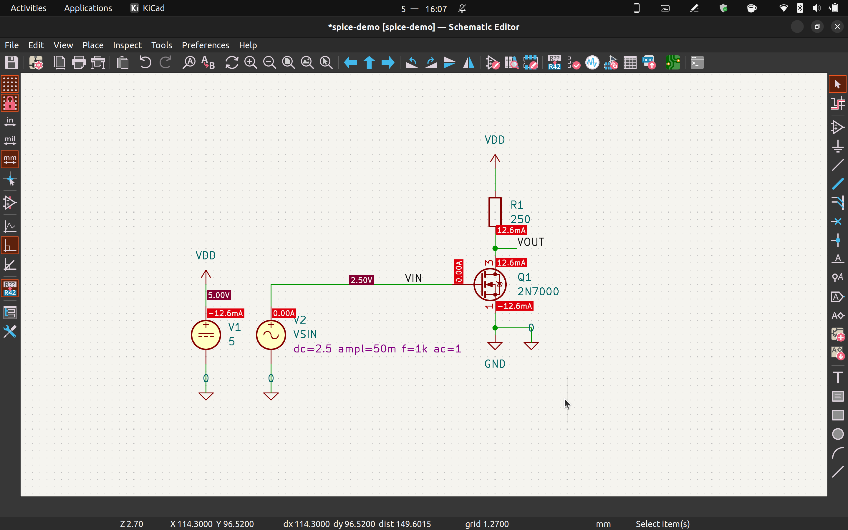
Build up your circuit schematic as usual, we will configure the simulation model later. If you need SPICE specific components such as voltage/current source, search "spice" in the symbol selector. In this example, let's build a simple common source amplifier with the 2N7000 N-channel MOSFET.
Voltage sources
For this amplifier, we need to add voltage sources for the power supply and the input signal. First, search "spice" in the symbol selector to find the voltage sources.
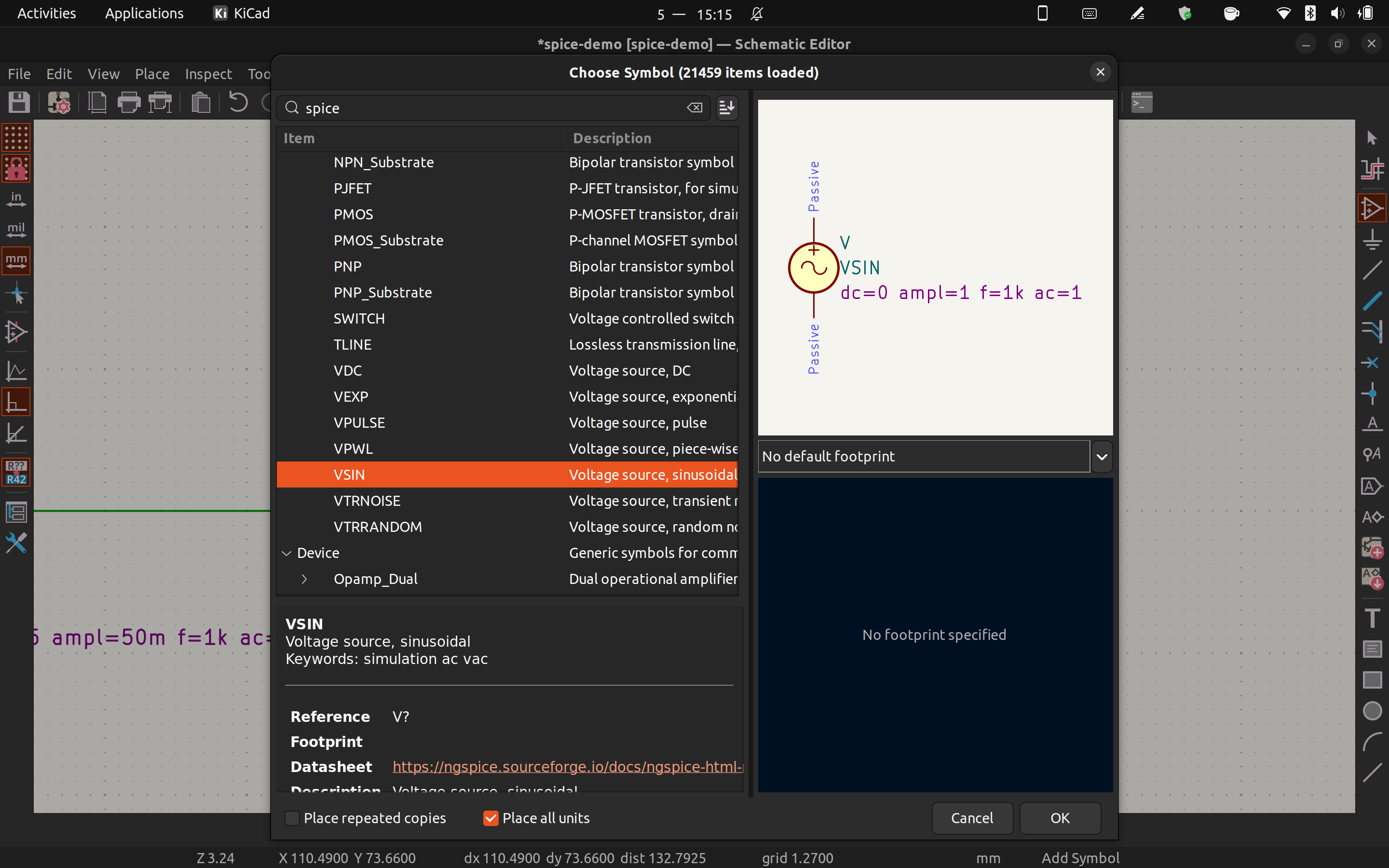
There are numerous options for voltage source. For the power supply we'll use "VDC" and for the input signal we'll use "VSIN". To configure the voltage, just put the voltage values in the component value field. The sinusoidal voltage can be configured by following the parameters on the component.
Component models
Unfortunately, Kicad doesn't have built-in component models for semiconductor devices. You can either configure the components yourself or find the component models online. Some manufacturers will have the SPICE model for their transistors and opamps available for download.
However, there is an easier way to find component models.
There is a repository on Github that collected lots of SPICE models.
Clone the repository and run Scripts/check_supported.py with python.
You can search for the component you want with this script.
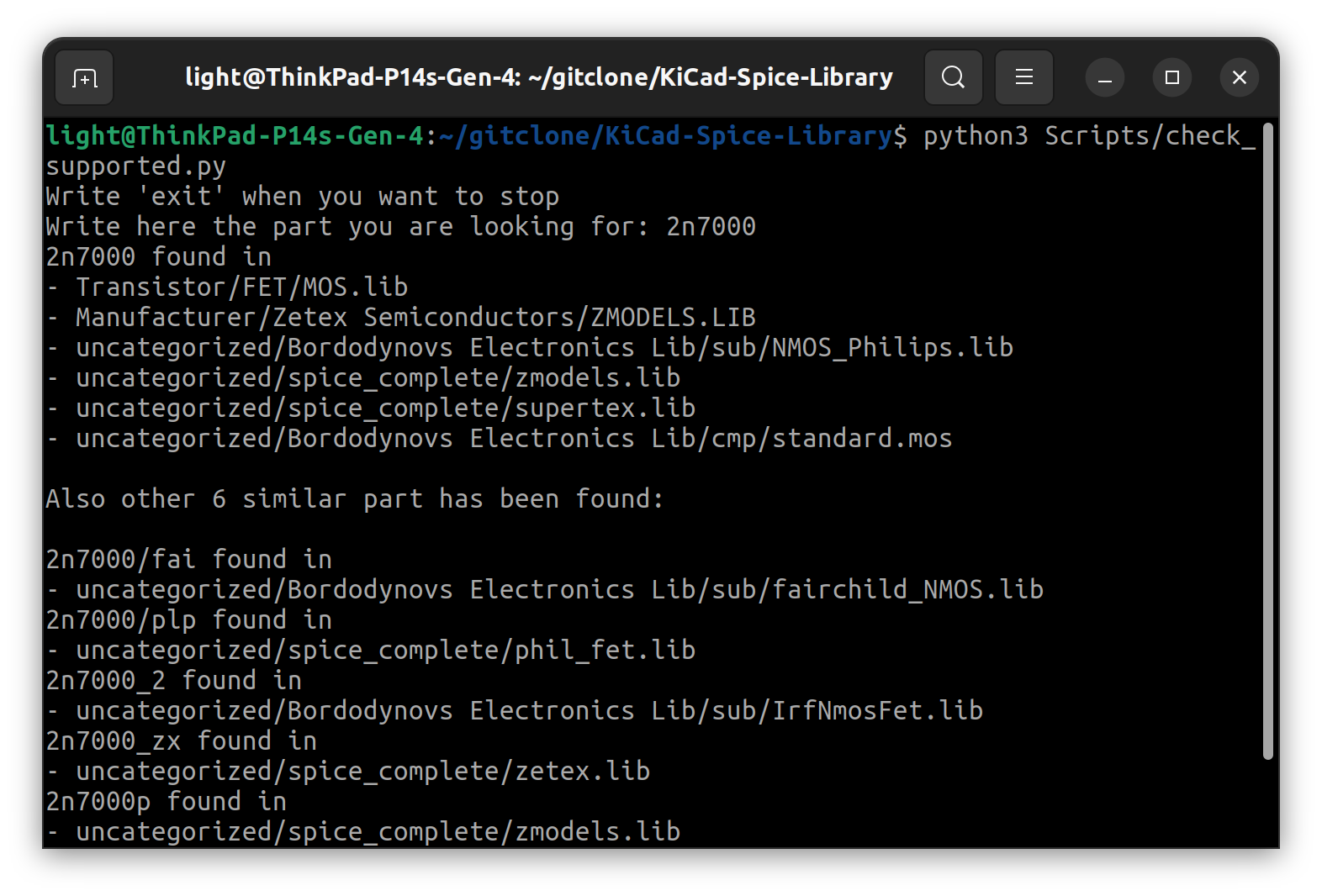
Typically, the script will return multiple results. Pick one and go to the file. With your text editor, copy the corresponding model into another file and save it under the Kicad project.
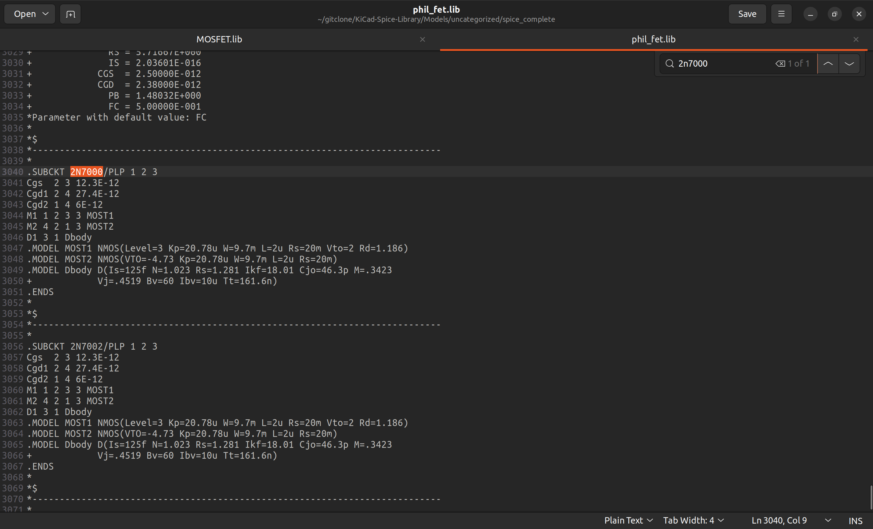
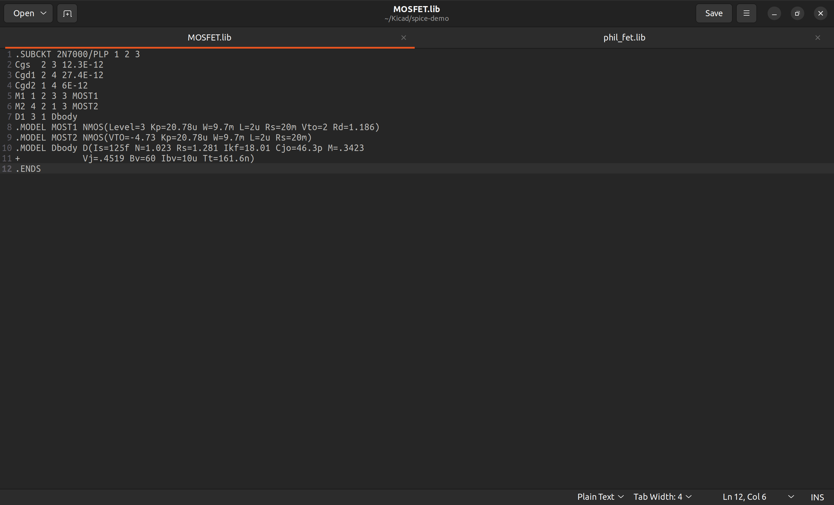
Note that the different search results may have slightly different component behaviour. Also, not all models work with the Ngspice simulator.
On the pin assignment page, we need to assign the pins on the model to the pins on the symbol. On SPICE models, the pins of a MOSFET is in the order of D-G-S, and it's E-B-C for BJT.
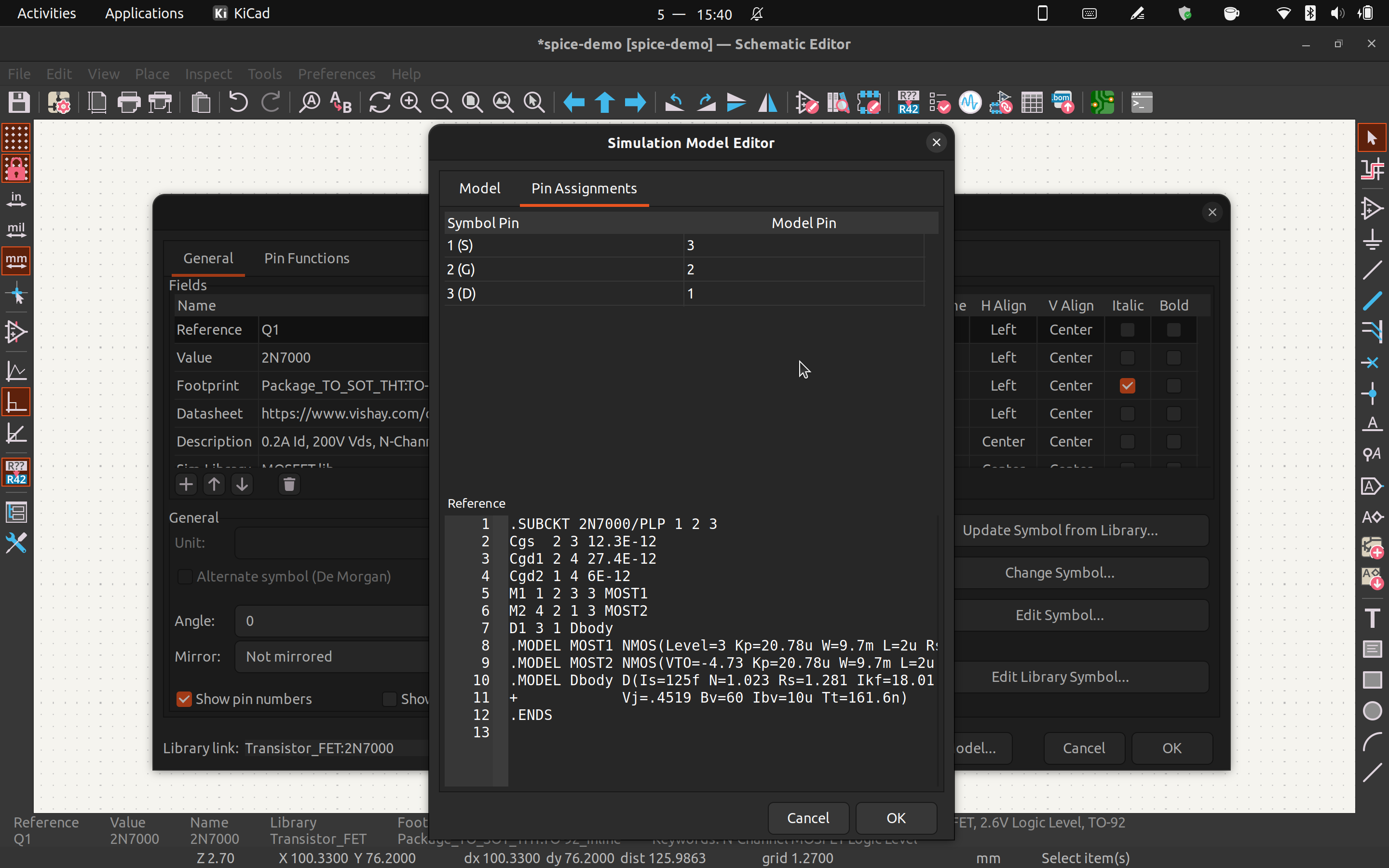
Click OK and save the changes, and we have a working schematic for simulation.
Simulation!
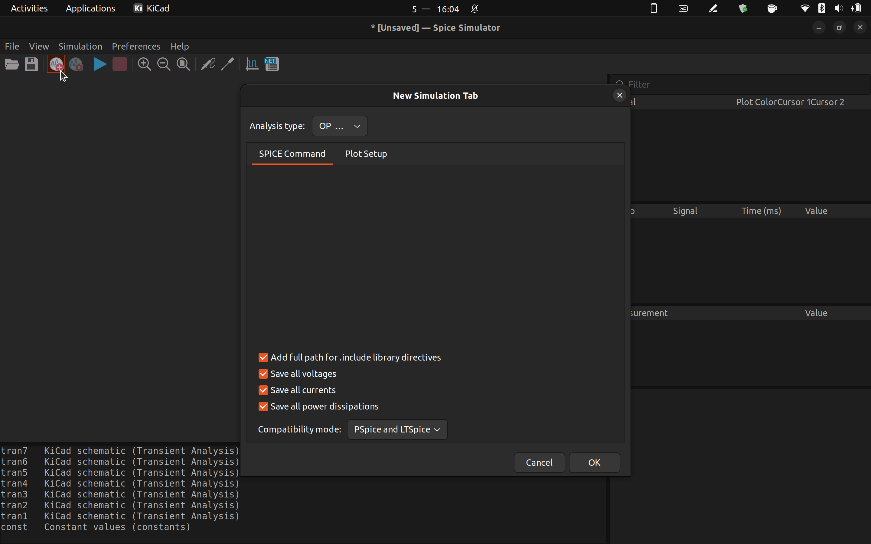
Open the simulator from the drop down menu.
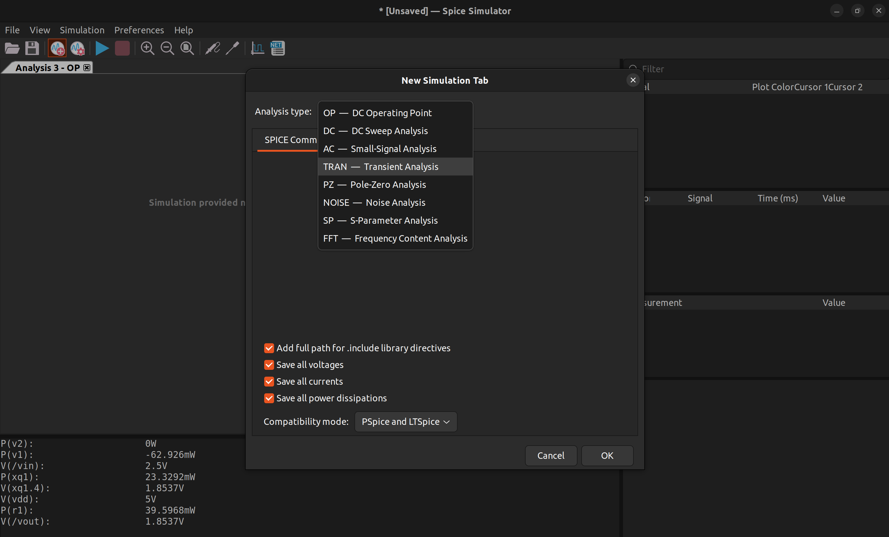
In the simulator, click new simulation tab to add a new simulation. First, let's run .op to find the DC operating point of the amplifier. Click OK and then click run, and the simulation result will show on the schematic.
Next, let's run .tran to simulate the time domain behaviour of this circuit.
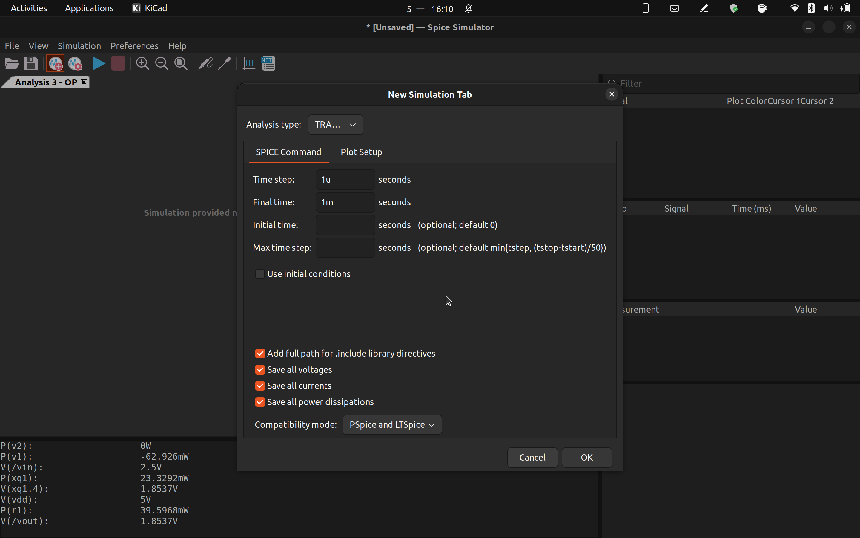
Set appropriate time step and simulation length for your circuit. Click OK and then click run, and the simulation result will show in the simulator.
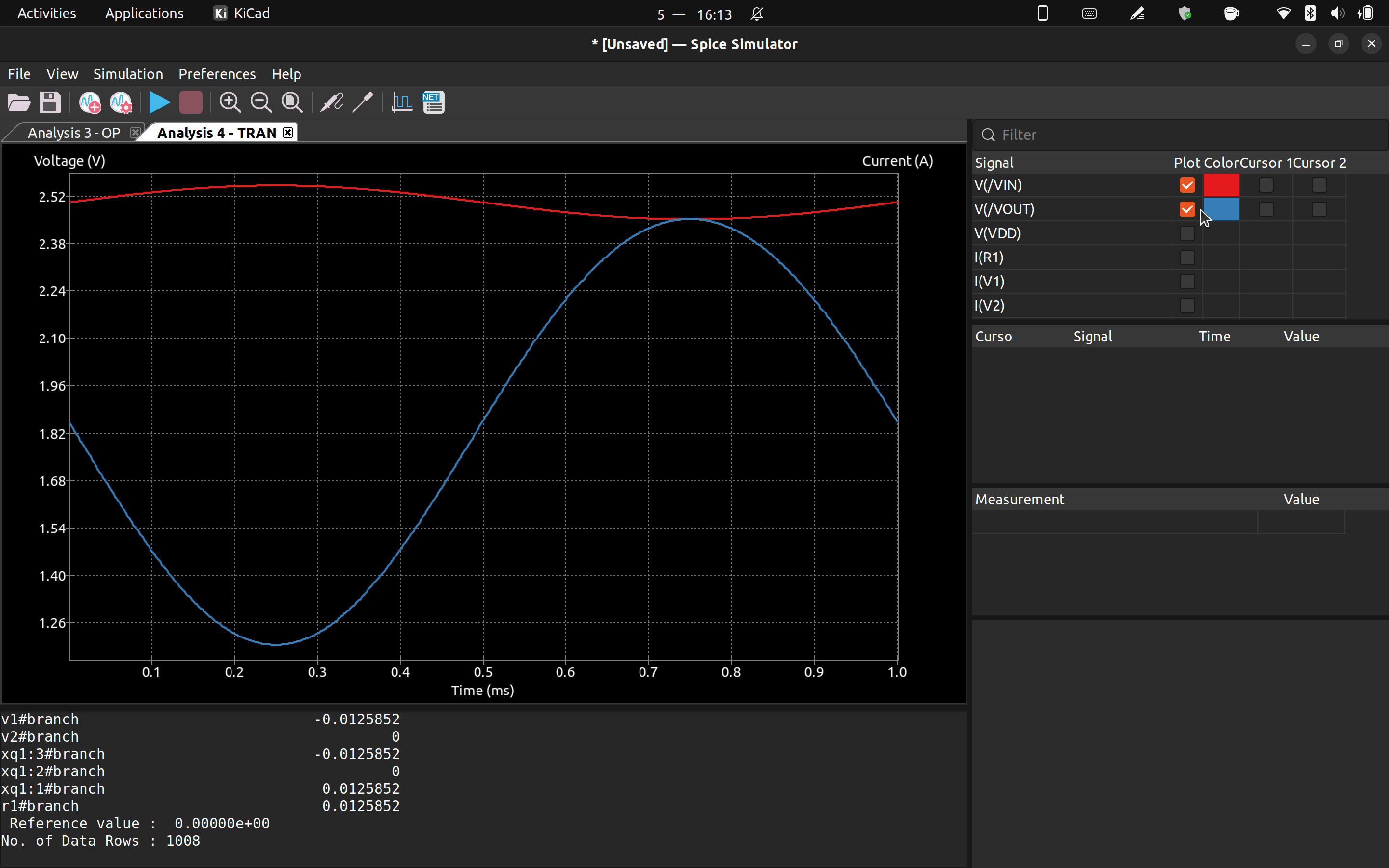
Remember to check the "plot" checkbox so that he signal will show on the plot.
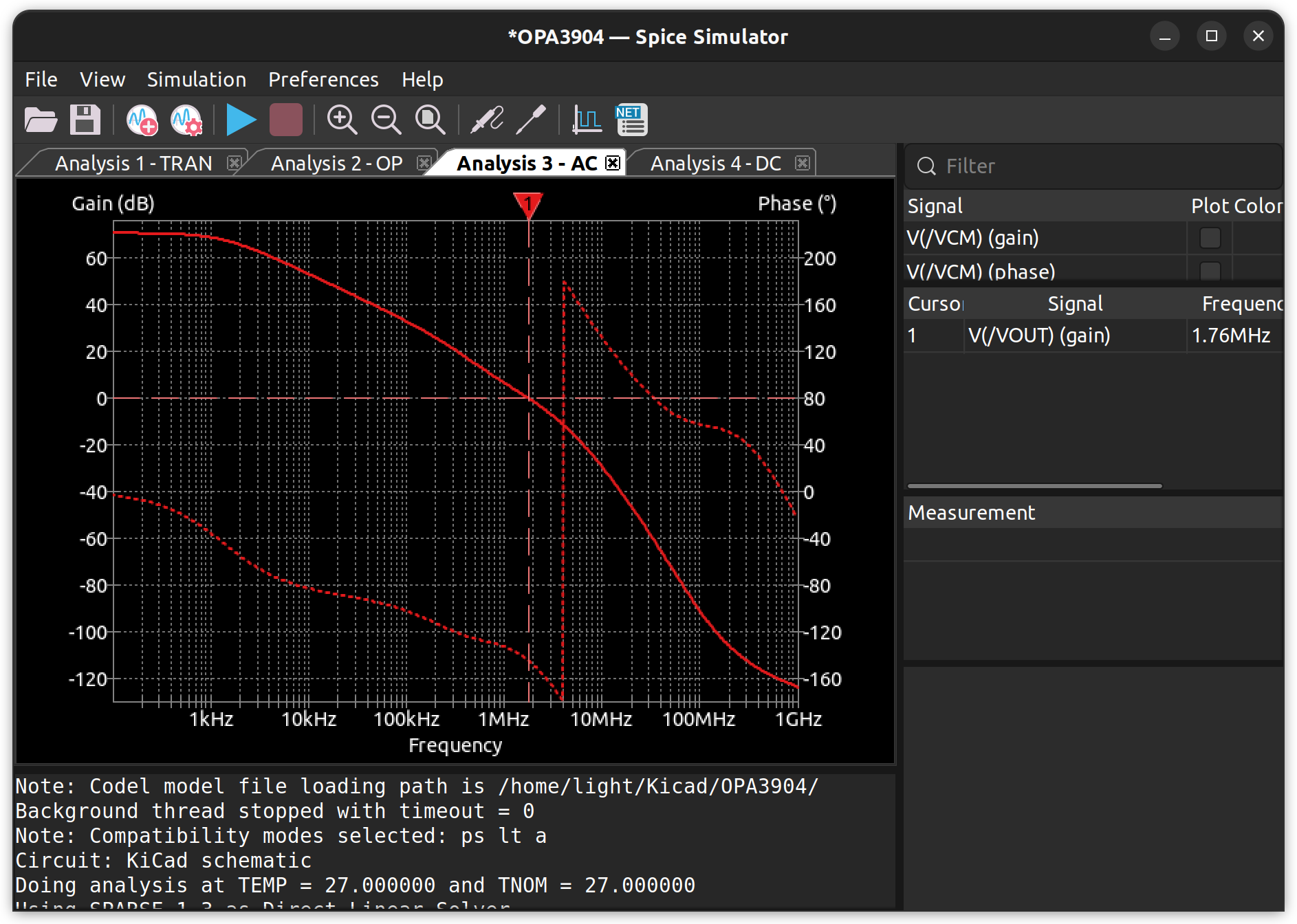
There are several other kinds of simulation that Kicad can do, such as .ac to find the Bode plot and .dc to do DC sweep. Just play around and find the best simulation option for yourself!