Driving a stepper motor with STM32's timer peripheral.
I was working on controlling some stepper motors on a robot. I wanted to control them with an STM32. The STM32 is controlled by a Raspberry Pi 5 with SPI. To generate the periodic signal for the stepper driver, I used the timer peripheral on the STM32. I this blog, I will go through the basics of the timer peripheral and how I set it up for this usage.
DRV8825 Stepper Motor Driver
The STM32 microcontroller cannot provide the necessary current and voltage for the stepper motor. Thus, We need an external driver IC to drive the stepper motor. I used a very common driver module based on Texas Instruments' DRV8825 IC.
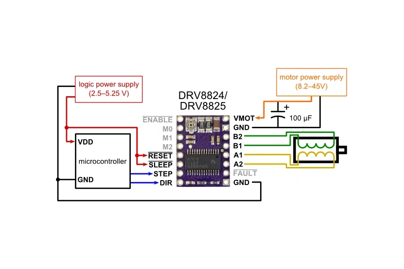
We only need to send two signals to the DRV8825 to spin the stepper motor. The DIR signal determines whether to spin clockwise or anti-clockwise. The STEP signal instructs the stepper motor to advance one step. When a pulse is sent to the STEP input, the stepper motor will advance one step. There are some other control signals for setting up microstepping or disabling the driver, please check out this article by Last Minute Engineers for more information. The connection between the STM32 and the DRV8825 module in this project is listed in the table below.

| DRV8825 | STM32 |
|---|---|
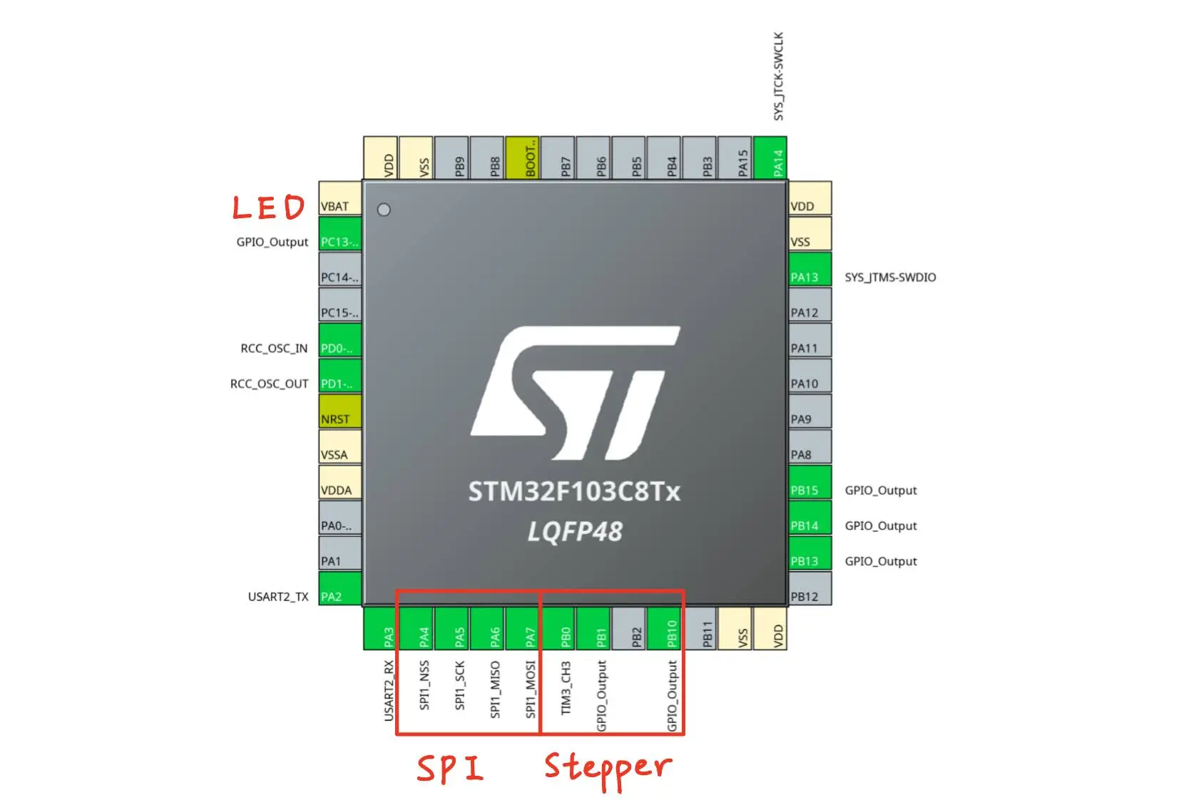
| ENb | PB1 |
| STEP | PB0 |
| DIR | PB10 |
Therefore, to spin the stepper motor at a controlled rate, all we need to do is to generate a periodic pulse signal. I am using a NEMA17 motor with 200 steps per revolution. Let's say we want to spin the motor at 2 revolution per second, we need to generate 400 pulse per second, that is one pulse every 2.5ms.
Why use the timer peripheral?
For any modern microcontroller, generating a pulse with 2.5ms period shouldn't be a hard task for the CPU. However, the CPU should be doing something more meaningful such as math calculations or decision making. An easy task like generating periodic pulse can be offloaded to the timer peripheral. All microcontrollers have some sort of timer peripheral, as it is so commonly used.
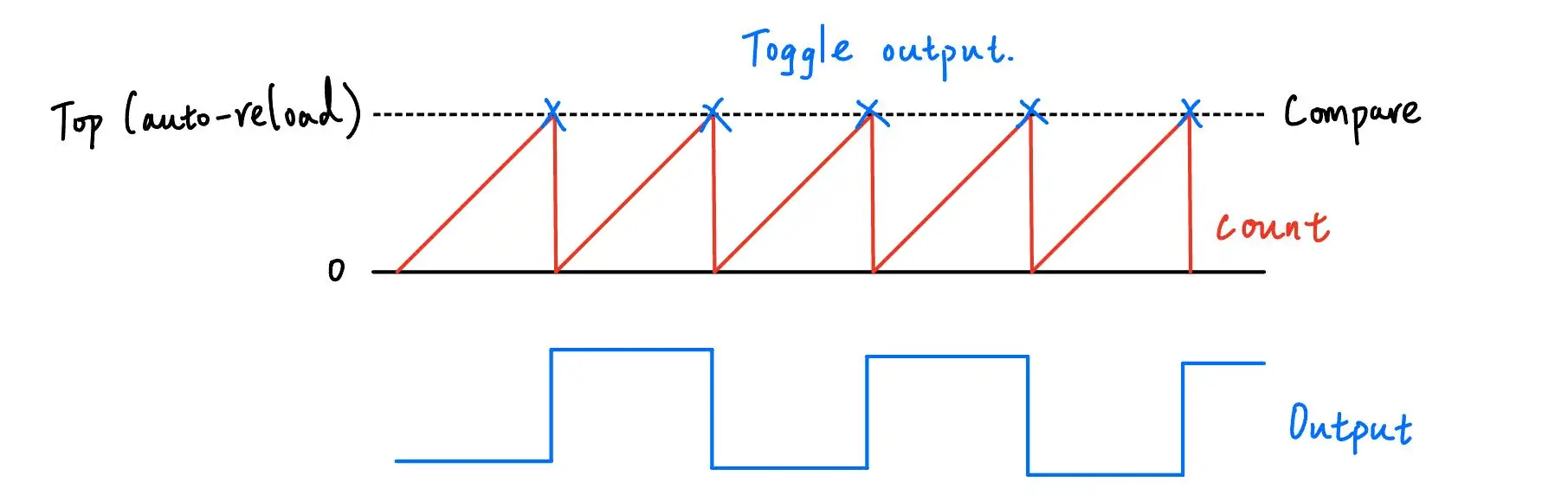
A timer is basically a counter that increments (or decrements) every clock cycle. We can set a value to compare with the counter, when they are the same, the microcontroller can trigger some specific actions. We can also set the top (auto reload) value of the counter, at which it will reset and count from the start again.

In our case, we are only interested in controlling the period, so we will set both the compare and top values to the same value. We will use the output compare mode and toggle the output pin when the counter counts to the top. This way, we can generate a pulse every two counter cycles.
Setting up the timer in STM32 Cube MX.
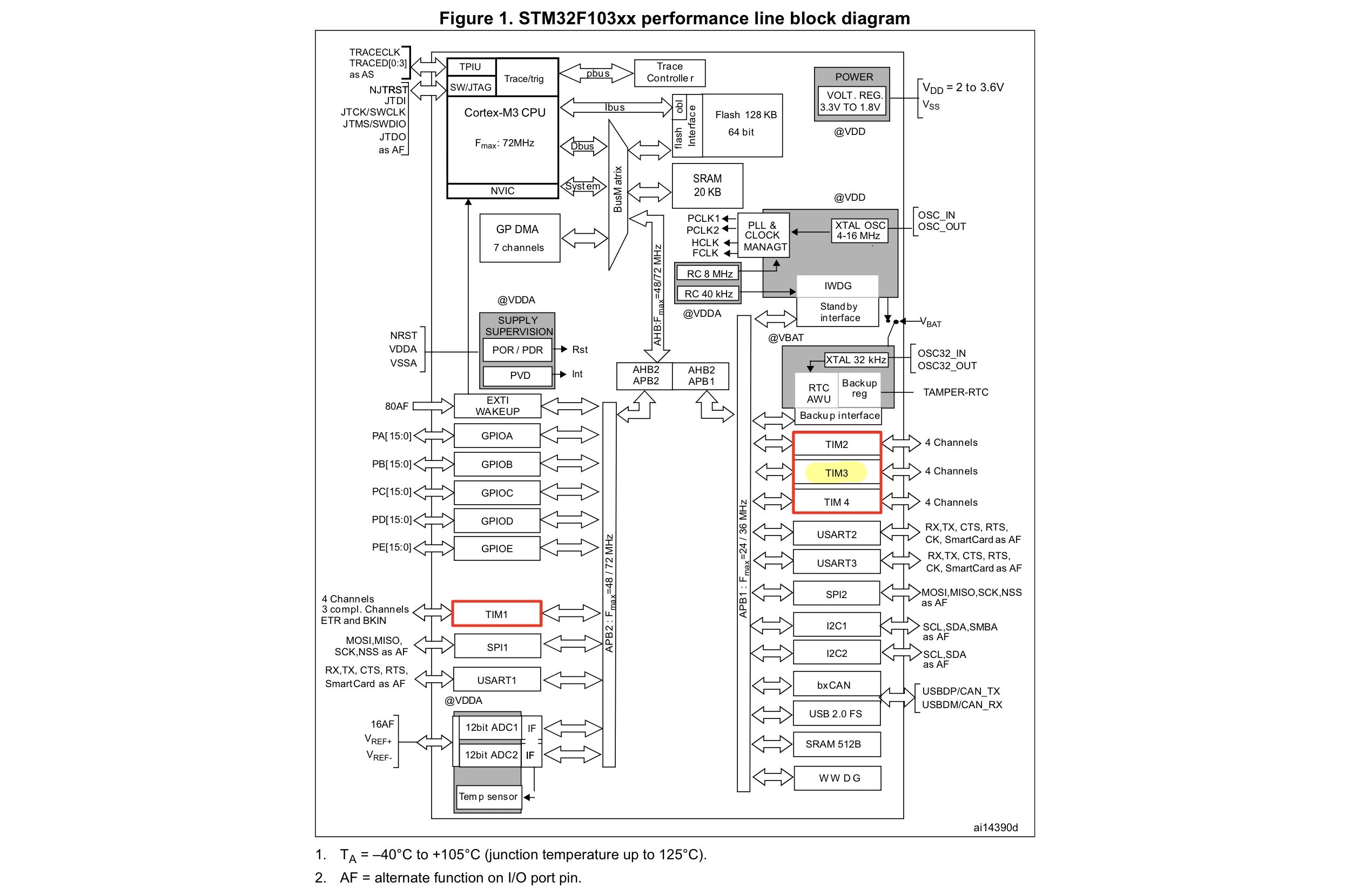
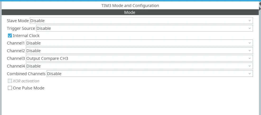
We are using the STM32F103C8T6 today, with the clock frequency set to 8MHz. TIM3 is used on the STM32, the pulse signal will be generated on its channel 3. Therefore, we need to enable TIM3 in Cube MX and set channel 3 to output compare mode. The pulse signal output will be on pin PB0. We also need to enable PB1, PB10, and PC13 as GPIO output for ENb, DIR, and LED, respectively.
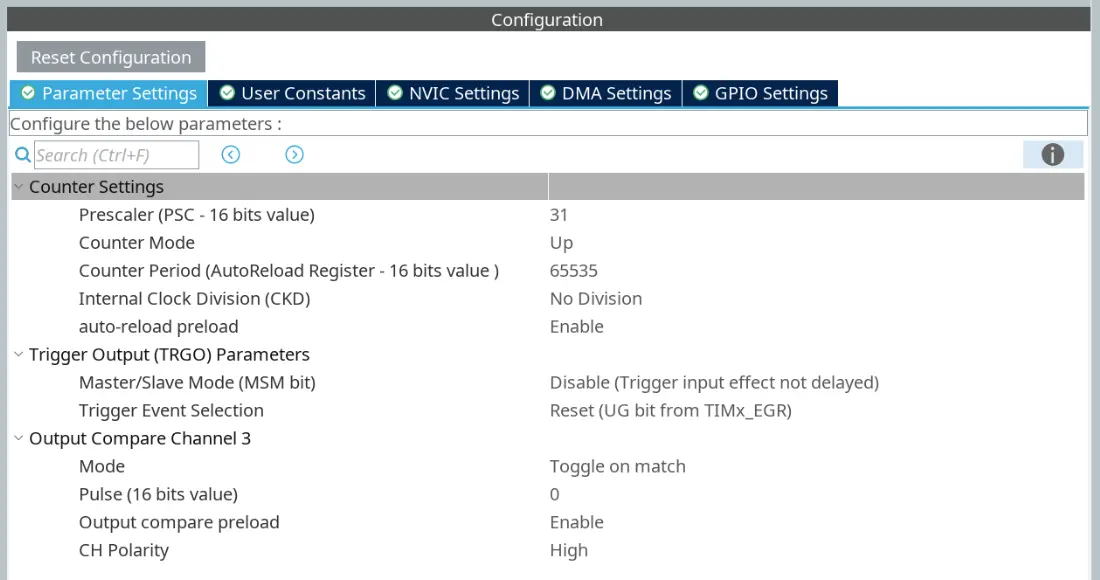
I figure that setting the pulse period resolution to 8us will give us a good balance between stepper motor speed range and precision. To achieve this, we need to slow down the clock for the TIM3 to 0.25MHz (4us per clock cycle) by setting the prescaler to 31. The prescaler will divided the 8MHz clock by a factor of 31 + 1 and give us the desired 0.25MHz clock. Since the pulse is generated every two counter cycles, the resolution will be 4us * 2 = 8us.
I will leave the counter period as default since it will be set on the fly in my code. Remember to enable auto-reload preload, this will prevent glitches when we change the auto-reload value. I will set the output compare mode to toggle on match and also enable output compare preload.
SPI slave mode.
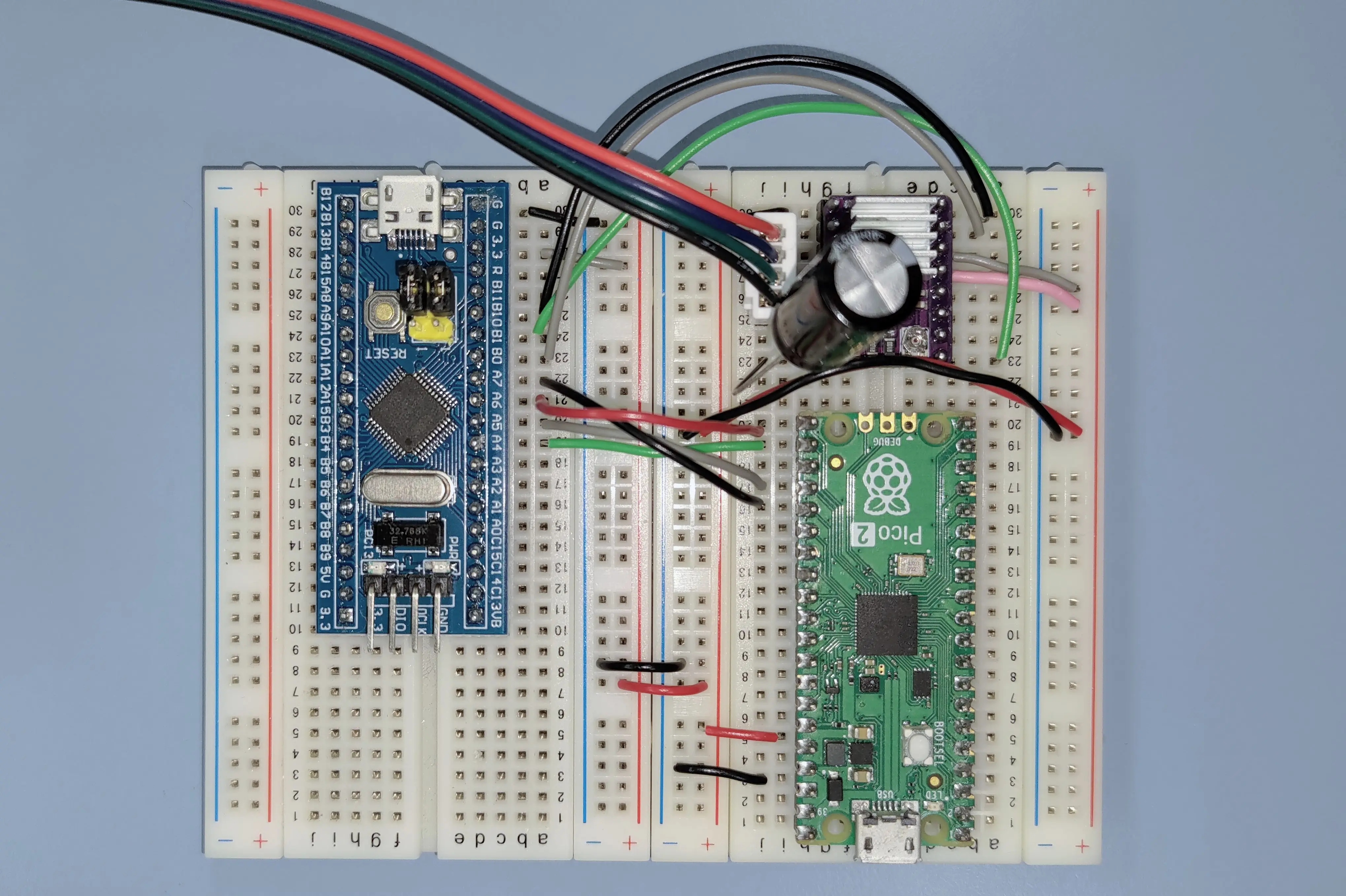
This project is a part of a robot whose central controller is a Raspberry Pi 5. The STM32F103C8T6 is an SPI slave and it will receive commands from the Pi 5 to spin the motor at the specified speed, but I will be testing it with a Pi Pico 2 as the master instead in this blog. I will go into the details of SPI slave mode operation in a future blog. Everytime an SPI frame is received on the STM32, it will trigger and interrupt and set the new compare and auto-reload values.

Changing the compare and auto-reload values.
The two values are stored at two specific memory addresses so that they can be accessed by the timer peripheral. Luckily, we can use some built-in functions to set them without knowing the addresses. I wrote a function using those built-in ones to set the two values.
void set_period(uint16_t period) {  // Sets the period for the step signal
    __HAL_TIM_SET_COMPARE(&htim3, TIM_CHANNEL_3, period);
    __HAL_TIM_SET_AUTORELOAD(&htim3, period);
}
Reference
- DRV8825 Datasheet.
- STM32F103 Reference Manual RM0008. The description of general-purpose timer is on page 365.